Dimensions Socket Weld Flanges & Stud Bolts ASME B16.5
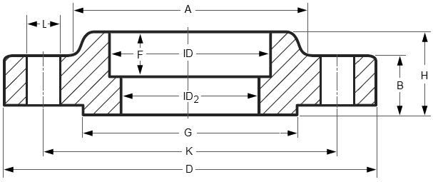
| CLass | 150 | 300 | 600 | 900 | 1500 | 2500 |
| DIA A |
30 | 38 | 38 | … | 38 | … |
| DIA D |
90 | 95 | 95 | … | 120 | … |
| THK B |
9.6 | 12.7 | 14.3 | … | 22.3 | … |
| 11.2 | 14.3 | 20.7 | … | 28.7 | … | |
| DIA G |
35.1 | 35.1 | 35.1 | … | 35.1 | … |
| DIA K |
60.3 | 66.7 | 66.7 | … | 82.6 | … |
| H | 14 | 21 | 22 | … | 32 | … |
| 15.6 | 22.6 | 28.4 | … | 38.4 | … | |
| NO. L |
4 | 4 | 4 | … | 4 | … |
| DIA L |
15.9 | 15.9 | 15.9 | … | 22.2 | … |
| Stud Bolts Diameter x Length | ||||||
| DIA (in) |
1/2 | 1/2 | 1/2 | … | 3/4 | … |
| Len mm |
55 | 65 | 75 | … | 110 | … |
| Other Diameters | |||||||
| NPS | 1/2 | 3/4 | 1 | 1.1/4 | 1.1/2 | 2 | 2.1/2 |
Notes..
- Dimensions are in millimeters unless otherwise indicated.
- The length of the Stud Bolt does not include the height of the chamfers (points).
- ID2 = Depending on the wall thickness of the pipe, must be specified by the purchaser.
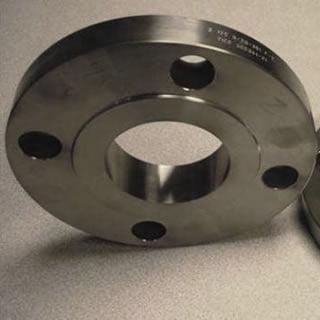
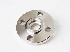
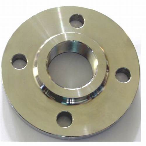
A socket weld flange is a type of pipe connector that incorporates a socket into which a pipe is welded. The inclusion of a socket in the socket weld flange creates a connection that is much stronger than a comparable slip-on flange. The socket weld flange was designed to work on small size, high-pressure pipelines. This flange is very popular in chemical plants where a smooth-flowing connection is needed in all flange joints. The benefit of a flanged connection is that the pipe can be easily disconnected at the flange and reassembled just as easily.
China Flange Manufacturer supplies ASME B16.5 ASTM B564 Hastelloy C276 Socket Weld Flange, 3 Inch, CL150.
Chemical Composition of Grade Hastelloy C276 (UNS N10276)
| C | Co | Cr | Fe | Mn | Mo | Ni | P | S | Si | V | W |
| Max | Max | Max | Max | Max | Max | Max | |||||
| 0.01% | 2.5% | 14.5%
-16.5% |
4-7% | 1.0% | 15 -17% | BAL | .04% | 0.03% | 0.08% | 0.35% | 3-4.5% |
| Hastelloy C276 Socket Weld Flange | ||
| 1 | Material: | Stainless Steel: such as 304, 304L, 316, 316L, 321 ,
310S, 904L, S31803, F51 and so on. |
| 2 | Standard: | GB, JIS, BS, DIN, ANSI and Non standard |
| 3 | ANSI Class: | 15, 030, 040, 060, 090 |
| 4 | Size: | 1/2″ – 24″ |
| 5 | Type: | Slip-on flanges, Blind flanges, Lap joint flanges,
Welding neck flanges,Plate flange, Socket welding flanges and Treaded flanges |
| 6 | Pressure ratings: | Class: 150 300 400 600 900 1500 and 2500
PN: 6 10 16 25 40 64 and 160 , 5K – 40K and so on |
| 7 | Sealing surface: | FF ,RF, LJ, FM , R.T.J , R.J and so on . |
| 8 | Production process: | raw material-cutting-heating-forging-heat treatment-maching-inspection. |
| 15 | Application: | petroleum, chemical, power, gas, water, linepipe, heat exchanger,
shipbuilding, construction, etc. |
| 16 | Tolerance: | not less than +_8% of normal wall thickness. |
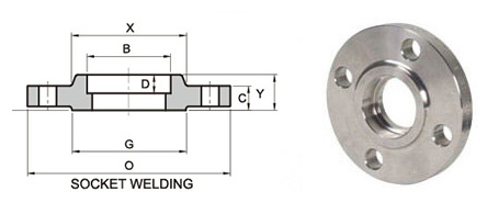
Dimensions of ANSI/ASME B16.5 Class 150 Socket Weld Flanges
| Pipe Normal Diam. | O.D. Flange | Thk. Of Flange Min | Diam. of Hub |
Diameter of Raised Face | Length Hub.Y | Bore | Depth of Socket.D |
Diam. of Bolt Circle |
Diam. of Bolt Holes |
Number of Bolts |
Diam. of Bolts (inch) |
KG | LB | |
| inch | dn | O | C | X | G | Y | B | D | BC | BH | BN | BD | ||
| 1/2″ | 15 | 89.00 | 11.20 | 30.20 | 35.10 | 15.70 | 22.40 | 9.70 | 60.50 | 15.80 | 4 | 1/2″ | 0.4 | 0.9 |
| 3/4″ | 20 | 98.50 | 12.70 | 38.10 | 42.90 | 15.70 | 27.70 | 11.20 | 69.90 | 15.80 | 4 | 1/2″ | 0.7 | 1.5 |
| 1″ | 25 | 108.00 | 14.20 | 49.30 | 50.80 | 17.50 | 34.50 | 12.70 | 79.30 | 15.80 | 4 | 1/2″ | 0.9 | 2 |
| 1-1/4″ | 32 | 117.50 | 15.70 | 58.70 | 63.50 | 20.60 | 43.20 | 14.20 | 88.90 | 15.80 | 4 | 1/2″ | 1.2 | 2.6 |
| 1-1/2″ | 40 | 127.00 | 17.50 | 65.00 | 73.20 | 22.40 | 49.50 | 15.80 | 98.60 | 15.80 | 4 | 1/2″ | 1.5 | 3.3 |
| 2″ | 50 | 152.50 | 19.10 | 77.70 | 91.90 | 25.40 | 62.00 | 17.50 | 120.70 | 19.10 | 4 | 5/8″ | 2.3 | 5.1 |
| 2-1/2″ | 65 | 178.00 | 22.40 | 90.40 | 104.60 | 28.40 | 74.70 | 19.10 | 139.70 | 19.10 | 4 | 5/8″ | 3.7 | 8.1 |
| 3″ | 80 | 190.50 | 23.90 | 108.00 | 127.00 | 30.20 | 90.70 | 20.60 | 152.40 | 19.10 | 4 | 5/8″ | 4.2 | 9.2 |
| 3-1/2″ | 90 | 216.00 | 23.90 | 122.20 | 139.70 | 31.80 | 103.40 | 177.80 | 19.10 | 8 | 5/8″ | 5.2 | 11.4 | |
| 4″ | 100 | 228.50 | 23.90 | 134.90 | 157.20 | 33.30 | 116.10 | 190.50 | 19.10 | 8 | 5/8″ | 5.9 | 13 | |
| 5″ | 125 | 254.00 | 23.90 | 163.60 | 185.70 | 36.60 | 143.80 | 215.90 | 22.40 | 8 | 3/4″ | 7 | 15.4 | |
| 6″ | 150 | 279.50 | 25.40 | 192.00 | 215.90 | 39.60 | 170.70 | 241.30 | 22.40 | 8 | 3/4″ | 8.4 | 18.5 | |
| 8″ | 200 | 343.00 | 28.40 | 246.10 | 269.70 | 44.50 | 221.50 | 298.50 | 22.40 | 8 | 3/4″ | 12.6 | 27.7 | |
| 10″ | 250 | 406.50 | 30.20 | 304.80 | 323.90 | 49.30 | 276.40 | 362.00 | 25.40 | 12 | 7/8″ | 18 | 39.6 | |
| 12″ | 300 | 482.50 | 31.80 | 365.30 | 381.00 | 55.60 | 327.20 | 431.80 | 25.40 | 12 | 7/8″ | 29.5 | 65 | |
| 14″ | 350 | 533.50 | 35.10 | 400.10 | 412.80 | 57.20 | 359.20 | 476.30 | 28.50 | 12 | 1″ | 38 | 84 | |
| 16″ | 400 | 597.00 | 36.60 | 457.20 | 469.90 | 63.50 | 410.50 | 539.80 | 28.50 | 16 | 1″ | 42 | 93 | |
| 18″ | 450 | 635.00 | 39.60 | 505.00 | 533.40 | 68.30 | 461.80 | 577.90 | 31.80 | 16 | 1 1/8″ | 54 | 120 | |
| 20″ | 500 | 698.50 | 42.90 | 558.80 | 584.20 | 73.20 | 513.10 | 635.00 | 31.80 | 20 | 1 1/8″ | 70 | 155 | |
| 24″ | 600 | 813.00 | 47.80 | 663.40 | 692.20 | 82.60 | 616.00 | 749.30 | 35.10 | 20 | 1 1/4″ | 94 | 207 | |
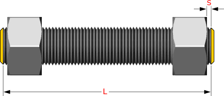
Studs are measured parallel to the axis (L) from
the first to the thread without the chamfers (points)
S = free threads equals 1/3 time bolt dia
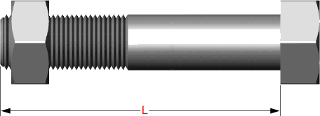
Hex bolts are measured from under the head to the top of de bolt
Dimensional Tolerances of Socket Weld Flanges ASME B16.5
Tolerances not listed in ASME B16.5 2013
≤ 24 = 1.6 mm
> 24 = ± 3.2 mm
≤ 10 = ± 0.8 mm
≥ 12 = + 1.6 mm / – 0 mm
≤ 12 = + 2.4 mm / – 1.6 mm
≥ 14 = ± 3.2 mm
Same as for Inside Diameter
Bolt Circle = 1.6 mm
Bolt Hole Spacing = ± 0.8 mm
≤ 2.1/2 = 0.8 mm max.
≥ 3 = 1.6 mm max.
≤ 18 = + 3.2 mm / – 0
≥ 20 = + 4.8 mm / – 0
≤ 18 = + 3.2 mm / – 0.8 mm
≥ 20 = + 4.8 mm / – 1.6 mm
1.6 mm Raised Face = ± 0.8 mm
6.35 mm Raised Face, Tongue and Groove / Male-Female = ± 0.4 mm

