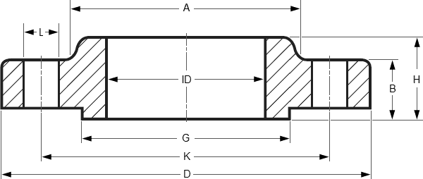
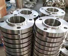
Dimensions Slip On Flanges & Stud Bolts ASME B16.5

| CLass | 150 | 300 | 600 | 900 | 1500 | 2500 |
| DIA A |
30 | 38 | 38 | 38 | 38 | … |
| DIA D |
90 | 95 | 95 | 120 | 120 | … |
| THK B |
9.6 | 12.7 | 14.3 | 22.3 | 22.3 | … |
| 11.2 | 14.3 | 20.7 | 28.7 | 28.7 | … | |
| DIA G |
35.1 | 35.1 | 35.1 | 35.1 | 35.1 | … |
| DIA K |
60.3 | 66.7 | 66.7 | 82.6 | 82.6 | … |
| H | 14 | 21 | 22 | 32 | 32 | … |
| 15.6 | 22.6 | 28.4 | 38.4 | 38.4 | … | |
| NO. L |
4 | 4 | 4 | 4 | 4 | … |
| DIA L |
15.9 | 15.9 | 15.9 | 22.2 | 22.2 | … |
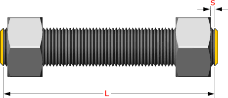
| Stud Bolts Diameter x Length | ||||||
| DIA (in) |
1/2 | 1/2 | 1/2 | 3/4 | 3/4 | … |
| Len mm |
55 | 65 | 75 | 110 | 110 | … |
| Other Diameters | |||||||
| NPS | 1/2 | 3/4 | 1 | 1.1/4 | 1.1/2 | 2 | 2.1/2 |
| 3 | 3.1/2 | 4 | 6 | 8 | 10 | 12 | |
| 14 | 16 | 18 | 20 | 24 | |||
Notes..
- Dimensions are in millimeters unless otherwise indicated.
- The length of the Stud Bolt does not include the height of the chamfers (points).
Composition ranges for 304L grade stainless steel
|
Grade |
C |
Mn |
Si |
P |
S |
Cr |
Mo |
Ni |
N |
|
|
304 |
min. max. |
– 0.08 |
– 2.0 |
– 0.75 |
– 0.045 |
– 0.030 |
18.0 20.0 |
– |
8.0 10.5 |
– 0.10 |
|
304L |
min. max. |
– 0.030 |
– 2.0 |
– 0.75 |
– 0.045 |
– 0.030 |
18.0 20.0 |
– |
8.0 12.0 |
– 0.10 |
|
304H |
min. max. |
0.04 0.10 |
– 2.0 |
– 0.75 |
-0.045 |
– 0.030 |
18.0 20.0 |
– |
8.0 10.5 |
– |
Mechanical properties of 304L grade stainless steel
|
Grade |
Tensile Strength (MPa) min |
Yield Strength 0.2% Proof (MPa) min |
Elongation (% in 50mm) min |
Hardness |
|
|
Rockwell B (HR B) max |
Brinell (HB) max |
||||
|
304 |
515 |
205 |
40 |
92 |
201 |
|
304L |
485 |
170 |
40 |
92 |
201 |
|
304H |
515 |
205 |
40 |
92 |
201 |
|
304H also has a requirement for a grain size of ASTM No 7 or coarser. |
|||||
Physical properties of 304L grade stainless steel in the annealed condition
|
Grade |
Density (kg/m3) |
Elastic Modulus (GPa) |
Mean Coefficient of Thermal Expansion (μm/m/°C) |
Thermal Conductivity (W/m.K) |
Specific Heat 0-100°C (J/kg.K) |
Electrical Resistivity (nΩ.m) |
|||
|
0-100°C |
0-315°C |
0-538°C |
at 100°C |
at 500°C |
|||||
|
304/L/H |
8000 |
193 |
17.2 |
17.8 |
18.4 |
16.2 |
21.5 |
500 |
720 |
Grade specifications for 304L grade stainless steel
|
Grade |
UNS No |
Old British |
Euronorm |
Swedish SS |
Japanese JIS |
||
|
BS |
En |
No |
Name |
||||
|
304 |
S30400 |
304S31 |
58E |
1.4301 |
X5CrNi18-10 |
2332 |
SUS 304 |
|
304L |
S30403 |
304S11 |
– |
1.4306 |
X2CrNi19-11 |
2352 |
SUS 304L |
|
304H |
S30409 |
304S51 |
– |
1.4948 |
X6CrNi18-11 |
– |
– |
|
These comparisons are approximate only. The list is intended as a comparison of functionally similar materials not as a schedule of contractual equivalents. If exact equivalents are needed original specifications must be consulted. |
|||||||
|
Type |
|
|
Size |
1/2″ to 120″ |
|
Standards |
SO, WN, SW, TH, LJ, BL, PL, etc |
|
Material |
Stainless Steel: ASTM A403 WP304, 304L, 310, 316, 316L, 321, 347, 904L Carbon Steel: ASTM A234 WPB, WPC ASTM A105 WPHY 42, 46, 52, 56, 60, 65, 70 Alloy Steel: ASTM A234 WP1, WP5, WP9, WP11, WP22, WP91 Duplex Stainless Steel: F51, 2205, F53, 2507, etc |
|
Sealing surface |
FF, RF, LJ, FM, R.T.J, R.J and so on |
|
Applications |
Petroleum,chemical,power,gas,metallurgy, shipbuilding, construction, etc |
Studs are measured parallel to the axis (L) from
the first to the thread without the chamfers (points)
S = free threads equals 1/3 time bolt dia

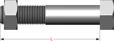
Hex bolts are measured from under the head to the top of de bolt

Tolerances not listed in ASME B16.5 2013
≤ 24 = 1.6 mm
> 24 = ± 3.2 mm
≤ 10 = ± 0.8 mm
≥ 12 = + 1.6 mm / – 0 mm
≤ 12 = + 2.4 mm / – 1.6 mm
≥ 14 = ± 3.2 mm
Same as for Inside Diameter
Bolt Circle = 1.6 mm
Bolt Hole Spacing = ± 0.8 mm
≤ 2.1/2 = 0.8 mm max.
≥ 3 = 1.6 mm max.
≤ 18 = + 3.2 mm / – 0
≥ 20 = + 4.8 mm / – 0
≤ 18 = + 3.2 mm / – 0.8 mm
≥ 20 = + 4.8 mm / – 1.6 mm
1.6 mm Raised Face = ± 0.8 mm
6.35 mm Raised Face, Tongue and Groove / Male-Female = ± 0.4 mm


