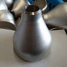
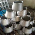
China Concentric Reducer Manufacturer wilson pipeline supplies ASME B16.9 ASTM B366 Nickel Alloy 200/201 Concentric Reducer, 4 Inch – 1-1/2 Inch, SCH80.
Nickel 200 and Nickel 201 are solid solution strengthened, commercially pure wrought materials. Typically, the elemental restrictions of both alloys are combined into one, dual-certified chemistry resulting in a single alloy with the desired characteristics of both alloys. Applications where Nickel 200/201 can be used include chemical processing and storage, synthetic fiber production, and processes where sodium hydroxide and fluorine is used. Other applications include aerospace and defense as well as food processing. Nickel 200/201 has exceptional resistance to caustic alkalies at various temperatures and concentrations.
When operating temperatures are expected to exceed 600°F, carbon content becomes critical. The lower carbon content of Nickel 201 makes the material resistant to graphitization and therefore less subject to embrittlement. Pressure vessels and vessel components can be constructed from Nickel 201 according to the ASME Boiler and Pressure Vessel Code, Section VIII, Division 1 for use up to 1250°F.
Resistance to Corrosion
Both Nickel 200 and 201 offer corrosion resistance in reducing and neutral media as well as in oxidizing atmospheres provided that the oxidizing media allows the formation of a passive oxide film. This oxide film accounts for the materials excellent resistance in caustic environments.
Fabrication and Heat Treatment
All hot working and cold working practices can be utilized when shaping Nickel 200/201. Hot working temperatures should be between 1200°F and 2250°F with heavy forming to be performed at temperatures
above 1600°F. Annealing should be performed at a temperature between 1300°F and 1600°F. Care should be taken when choosing the anneal temperature and time-at-temperature for this can greatly influence the mechanical properties and structure of the material.
| STANDARD | UNS | WERKSTOFF NR. | BS | AFNOR | JIS | GOST | EN |
| Nickel 200 | N02200 | 2.4066 | NA 11 | N-100M | NW 2200 | НП-2 | Ni 99.2 |
| Nickel 201 | N02201 | 2.4068 | NA 12 | – | NW 2201 | НП-2 | LC-Ni 99 |
Chemical Composition, % of Inconel 600 (UNS N06600/Alloy 600)
| Nickel 200 (UNS N02200) | 99.0 min | .40 max | .25 max | .15 max | .35 max | .01 max | .35 max |
| NI | FE | CU | C | MN | S | SI | |
| Nickel 201 (UNS N02201) | 99.0 min | .40 max | .25 max | .02 max | .35 max | .01 max | .35 max |
| Size: | 4″ – 1-1/2″ (DN100-DN40) |
| Material: |
Carbon Steel: ASTM: SA105N/A105, ASTM SA350 LF2,etc Stainless Steel: ASTM A182 F304/304L/316/316L, etc Alloy Steel: ASTM A182 F1/F5/F9/F11/F22/F91, Etc. Duplex stainless steel: ASTM A182 F51/F53/F55/F60, etc Super Duplex Stainless Steel: S32750/2507, UNS32760, etc Nicke alloys: Nickel 200, Monel 400, Inconel 600/625, Incoloy 825/800, Hastelloy C276, Hastelloy C276, Hastelloy B1/B2/B3, Alloy 20, etc Cu-Ni: 90/10,70/30, etc |
| Standard: | ASME/DIN/ISO/, etc |
| Connection: | Welding |
| Wall thickness: | SCH40 |
| Finish: | Mirror polish, semi bright etc |
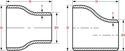
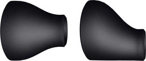
Dimensions Butt Weld Reducers Concentric and Eccentric ASME B16.9

| NPS | O.D. D |
O.D. D1 |
Length H |
| 3/4 ▸ 1/2 | 26.7 | 21.3 | 38 |
| 1 ▸ 1/2 | 33.4 | 21.3 | 51 |
| 1 ▸ 3/4 | 33.4 | 26.7 | 51 |
| 1.1/4 ▸ 1/2 | 42.2 | 21.3 | 51 |
| 1.1/4 ▸ 3/4 | 42.2 | 26.7 | 51 |
| 1.1/4 ▸ 1 | 42.2 | 33.4 | 51 |
| 1.1/2 ▸ 1/2 | 48.3 | 21.3 | 64 |
| 1.1/2 ▸ 3/4 | 48.3 | 26.7 | 64 |
| 1.1/2 ▸ 1 | 48.3 | 33.4 | 64 |
| 1.1/2 ▸ 1.1/4 | 48.3 | 42.2 | 64 |
| 2 ▸ 3/4 | 60.3 | 26.7 | 76 |
| 2 ▸ 1 | 60.3 | 33.4 | 76 |
| 2 ▸ 1.1/4 | 60.3 | 42.2 | 76 |
| 2 ▸ 1.1/2 | 60.3 | 48.3 | 76 |
| 2.1/2 ▸ 1 | 73 | 33.4 | 89 |
| 2.1/2 ▸ 1.1/4 | 73 | 42.2 | 89 |
| 2.1/2 ▸ 1.1/2 | 73 | 48.3 | 89 |
| 2.1/2 ▸ 2 | 73 | 60.3 | 89 |
| 3 ▸ 1.1/4 | 88.9 | 42.2 | 89 |
| 3 ▸ 1.1/2 | 88.9 | 48.3 | 89 |
| 3 ▸ 2 | 88.9 | 60.3 | 89 |
| 3 ▸ 2.1/2 | 88.9 | 73 | 89 |
| 3.1/2 ▸ 1.1/4 | 101.6 | 42.2 | 102 |
| 3.1/2 ▸ 1.1/2 | 101.6 | 48.3 | 102 |
| 3.1/2 ▸ 2 | 101.6 | 60.3 | 102 |
| 3.1/2 ▸ 2.1/2 | 101.6 | 73 | 102 |
| 3.1/2 ▸ 3 | 101.6 | 88.9 | 102 |
| 4 ▸ 1.1/2 | 114.3 | 48.3 | 102 |
| 4 ▸ 2 | 114.3 | 60.3 | 102 |
| 4 ▸ 2.1/2 | 114.3 | 73 | 102 |
| 4 ▸ 3 | 114.3 | 88.9 | 102 |
| 4 ▸ 3.1/2 | 114.3 | 101.6 | 102 |
| 5 ▸ 2 | 141.3 | 60.3 | 127 |
| 5 ▸ 2.1/2 | 141.3 | 73 | 127 |
| 5 ▸ 3 | 141.3 | 88.9 | 127 |
| 5 ▸ 3.1/2 | 141.3 | 101.6 | 127 |
| 5 ▸ 4 | 141.3 | 114.3 | 127 |
| 6 ▸ 2.1/2 | 168.3 | 73 | 140 |
| 6 ▸ 3 | 168.3 | 88.9 | 140 |
| 6 ▸ 3.1/2 | 168.3 | 101.6 | 140 |
| 6 ▸ 4 | 168.3 | 114.3 | 140 |
| 6 ▸ 5 | 168.3 | 141.3 | 140 |
| 8 ▸ 3.1/2 | 219.1 | 101.6 | 152 |
| 8 ▸ 4 | 219.1 | 114.3 | 152 |
| 8 ▸ 5 | 219.1 | 141.3 | 152 |
| 8 ▸ 6 | 219.1 | 168.3 | 152 |
| 10 ▸ 4 | 273 | 114.3 | 178 |
| 10 ▸ 5 | 273 | 141.3 | 178 |
| 10 ▸ 6 | 273 | 168.3 | 178 |
| 10 ▸ 8 | 273 | 219.1 | 178 |
| 12 ▸ 5 | 323.9 | 141.3 | 203 |
| 12 ▸ 6 | 323.9 | 168.3 | 203 |
| 12 ▸ 8 | 323.9 | 219.1 | 203 |
| 12 ▸ 10 | 323.9 | 273 | 203 |
| 14 ▸ 6 | 355.6 | 168.3 | 330 |
| 14 ▸ 8 | 355.6 | 219.1 | 330 |
| 14 ▸ 10 | 355.6 | 273 | 330 |
| 14 ▸ 12 | 355.6 | 323.9 | 330 |
| 16 ▸ 8 | 406.4 | 219 | 356 |
| 16 ▸ 10 | 406.4 | 273 | 356 |
| 16 ▸ 12 | 406.4 | 323.9 | 356 |
| 16 ▸ 14 | 406.4 | 355.6 | 356 |
| 18 ▸ 10 | 457 | 273 | 381 |
| 18 ▸ 12 | 457 | 323.9 | 381 |
| 18 ▸ 14 | 457 | 355.6 | 381 |
| 18 ▸ 16 | 457 | 406.4 | 381 |
| 20 ▸ 12 | 508 | 323.9 | 508 |
| 20 ▸ 14 | 508 | 355.6 | 508 |
| 20 ▸ 16 | 508 | 406.4 | 508 |
| 20 ▸ 18 | 508 | 457 | 508 |
| 22 ▸ 14 | 559 | 355.6 | 508 |
| 22 ▸ 16 | 559 | 406.4 | 508 |
| 22 ▸ 18 | 559 | 457 | 508 |
| 22 ▸ 20 | 559 | 508 | 508 |
| 24 ▸ 16 | 610 | 406.4 | 508 |
| 24 ▸ 18 | 610 | 457 | 508 |
| 24 ▸ 20 | 610 | 508 | 508 |
| 24 ▸ 22 | 610 | 559 | 508 |
| 26 ▸ 18 | 660 | 457 | 610 |
| 26 ▸ 20 | 660 | 508 | 610 |
| 26 ▸ 22 | 660 | 559 | 610 |
| 26 ▸ 24 | 660 | 610 | 610 |
| 28 ▸ 18 | 711 | 457 | 610 |
| 28 ▸ 20 | 711 | 508 | 610 |
| 28 ▸ 24 | 711 | 610 | 610 |
| 28 ▸ 26 | 711 | 660 | 610 |
| 30 ▸ 20 | 762 | 508 | 610 |
| 30 ▸ 24 | 762 | 610 | 610 |
| 30 ▸ 26 | 762 | 660 | 610 |
| 30 ▸ 28 | 762 | 711 | 610 |
| 32 ▸ 24 | 813 | 610 | 610 |
| 32 ▸ 26 | 813 | 660 | 610 |
| 32 ▸ 28 | 813 | 711 | 610 |
| 32 ▸ 30 | 813 | 762 | 610 |
| 34 ▸ 24 | 864 | 610 | 610 |
| 34 ▸ 26 | 864 | 660 | 610 |
| 34 ▸ 30 | 864 | 762 | 610 |
| 34 ▸ 32 | 864 | 813 | 610 |
| 36 ▸ 24 | 914 | 610 | 610 |
| 36 ▸ 26 | 914 | 660 | 610 |
| 36 ▸ 30 | 914 | 762 | 610 |
| 36 ▸ 32 | 914 | 813 | 610 |
| 36 ▸ 34 | 914 | 864 | 610 |
| 38 ▸ 26 | 965 | 660 | 610 |
| 38 ▸ 28 | 965 | 711 | 610 |
| 38 ▸ 30 | 965 | 762 | 610 |
| 38 ▸ 32 | 965 | 813 | 610 |
| 38 ▸ 34 | 965 | 864 | 610 |
| 38 ▸ 36 | 965 | 914 | 610 |
| 40 ▸ 30 | 1016 | 762 | 610 |
| 40 ▸ 32 | 1016 | 813 | 610 |
| 40 ▸ 34 | 1016 | 864 | 610 |
| 40 ▸ 36 | 1016 | 914 | 610 |
| 40 ▸ 38 | 1016 | 965 | 610 |
| Dimensions are in millimeters unless otherwise indicated. Wall thickness (t) must be specified by customer. | |||

| Dimensional Tolerances of Concentric and Eccentric Reducers ASME B16.9 | ||||
| Nominal Pipe Size | 1/2 to 2.1/2 | 3 to 3.1/2 | 4 | 5 to 8 |
| Outside Diameter at Bevel (D) |
+ 1.6 – 0.8 |
1.6 | 1.6 | + 2.4 – 1.6 |
| Inside Diameter at End | 0.8 | 1.6 | 1.6 | 1.6 |
| Overall Length (H) | 2 | 2 | 2 | 2 |
| Nominal Pipe Size | 10 to 18 | 20 to 24 | 26 to 30 | 32 to 48 |
| Outside Diameter at Bevel (D) |
+ 4 – 3.2 |
+ 6.4 – 4.8 |
+ 6.4 – 4.8 |
+ 6.4 – 4.8 |
| Inside Diameter at End | 3.2 | 4.8 | + 6.4 – 4.8 |
+ 6.4 – 4.8 |
| Overall Length (H) | 2 | 2 | 5 | 5 |
| Wall Thickness (t) | Not less than 87.5% of Nominal Wall Thickness | |||
| Dimensional tolerances are in millimeters unless otherwise indicated and are equal ± except as noted. | ||||


评价
目前还没有评价